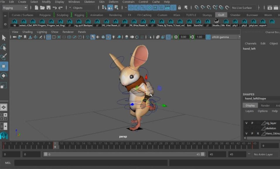
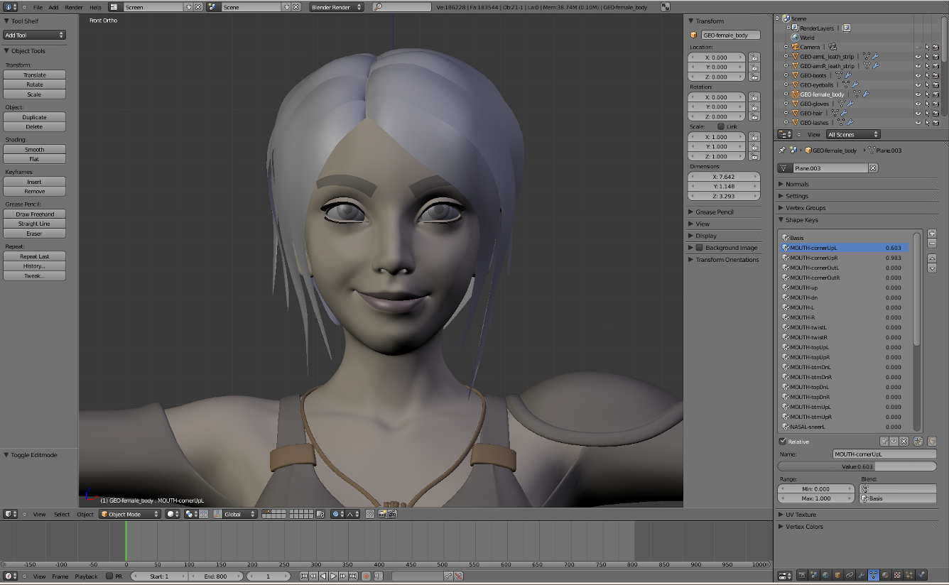
(See Drawing Basic Shapes and Pushing and Pulling Shapes into 3D for help.) With the Select tool , triple-click the first volume, which will be your cutting object. In this example, the cutting object is the cylinder, as shown in the figure. Move and rotate your cutting shape so that it. Another powerful, cross-platform, open source 2D animation drawing and animation tool is Synfig Studio. Although more complicated than most other graphics apps, Synfig gives you control over almost every aspect of your animation, and provides you with familiar tools like brushes, fills, masking, layers and more. Blendshapes (known as blend shapes on Maya or morph targets on 3DS Max) are commonly used in 3D animation tools, though their name varies from one 3D software to another. They use the deformations of a 3D shape to show different expressions and visemes. Create 3D objects. 3D effects enable you to create three-dimensional (3D) objects from two.
Download 49,515 3d shapes free vectors. Choose from over a million free vectors, clipart graphics, vector art images, design templates, and illustrations created by artists worldwide!
With SketchUp’s Solid tools, you can create new shapes by combining or cutting one shape with another, making it easy to model an outer shell or joinery.
In SketchUp, a solid is any 3D model (component or group) that has a finite closed volume. A SketchUp solid cannot have any leaks (missing faces or faces that do not meet at an edge). The following image contains several solids.
Check out the following table for a quick introduction to the Solid Tools, including what the tool does and whether it’s available in SketchUp Free.
Tool | Name | What It Does | Included in SketchUp Free? |
---|---|---|---|
Outer Shell | Leaves only the outer faces of overlapping solids. | Yes | |
Union | Combines two or more solids into a single form. | Paid subscriptions only | |
Subtract | One solid removes part of another and is deleted. | Paid subscriptions only. In SketchUp Free, use Intersect with Model. | |
Trim | One solid trims another but remains in the model. | Paid subscriptions only | |
Intersect | Leaves only the intersecting geometry. | Paid subscriptions only | |
Split | Splits solids along intersecting geometry. | Paid subscriptions only |
To find the Solid Tools, look in the following parts of the SketchUp interface:
- Solids toolbar
- Tools menu (Select Tools > Outer Shell or Select Tools > Solid Tools and select the other tools from a submenu)
- Tool palette (macOS)
- Solids toolbar in the left-hand tray
- Solid Inspector utility in the right-hand panel
In the following video, you see examples of the Solid tools in action. In the following sections of this article, you will find steps and details about using each tool. (Note, however, that you can't place SketchUp models in Google Earth anymore.)
Table of Contents
Creating an outer shell
The Outer Shell tool () removes geometry inside overlapping groups or components, leaving only the outer faces.
For example, say you have two models: One is a detailed interior and exterior building model. The other model illustrates the building in a street view that shows surrounding buildings, streets, and landscaping. You can import the detailed building model into your street view. However, all that geometry might slow down your street view model and isn’t necessary. In your street view, creating an outer shell of the building eliminates the interior geometry you don’t need so that your street view model is lighter and renders faster as you work on it.
To create an outer shell from overlapping groups or components, follow these steps:
- With the Select tool (), select all the intersecting groups or components you want to include in your outer shell.
- Context-click your selection and choose Outer Shell from the menu that appears, as shown in the figure. The outer faces remain.
Or, you can create an outer shell as follows:
- Select the Outer Shell tool ().Tip: Until you hover over a solid group or component, you see an arrow cursor with a circle and a slash. When your cursor hovers over a solid group or component, the red circle and slash change to a black 1 inside a circle, and you see a Solid Group or Solid Component ScreenTip.
- Click to select the first group or component in your outer shell.
- Click the second group or component. SketchUp combines your selections into an outer shell so that only the outer faces remain.
- (Optional) Continue clicking additional groups or components to add them to your outer shell, as shown in the figure.
- Select the Outer Shell tool () from the left hand tool tray.Tip: Until you hover over a solid group or component, you see an arrow cursor with a circle and a slash. When your cursor hovers over a solid group or component, the red circle and slash change to a black 1 inside a circle, and you see a Solid Group or Solid Component ScreenTip.
- Click to select the first group or component in your outer shell.
- Click the second group or component. SketchUp combines your selections into an outer shell so that only the outer faces remain.
- (Optional) Continue clicking additional groups or components to add them to your outer shell, as shown in the figure.
Uniting solids into a single form
A union merges two or more solid entities into a single solid.
The result of a union is similar to the result of an outer shell. However, the result of a union can contain internal geometry whereas an outer shell contains only external faces. (See the preceding figure for an example.)
Here’s how to use the Union tool to combine solid entities:
- Select the Union tool ().Tip: Until you hover over a solid group or component, you see an arrow cursor with a circle and a slash. When your cursor hovers over a solid group or component, the red circle and slash change to a black 1 inside a circle, and you see a Solid Group or Solid Component ScreenTip.
- Click to select the first group or component for the union.
- Click the second group or component. The resulting union of the geometry remains.
- (Optional) Continue clicking additional groups or components to add them to the union, as shown in the figure, which uses X-Ray view so that you can see the geometry within each solid.
3d Shape Animation Tool Template
Subtracting one solid from another (or use Intersect Faces with Model)
With the Subtract tool, you can use one solid entity to cut another solid entity. Your original solid entity is then subtracted from the model. For the subtraction to work, the two solids need to overlap.
To perform a subtraction, follow these steps:
- Select the Subtract tool ().Tip: Until you hover over a solid group or component, you see an arrow cursor with a circle and a slash. When your cursor hovers over a solid group or component, the red circle and slash change to a black 1 inside a circle, and you see a Solid Group or Solid Component ScreenTip.
- Click to select the cutting group or component. In the example shown here, select the peg first to make a hole in the board. After you make a selection, the 1 next to the cursor becomes a 2.
- Click the group or component that you want to cut. The cutting group disappears, but makes a hole in the second selection. In this example, you see a peg-sized hole in the board.
If you’re using SketchUp Free, you can create the effect of a subtraction by using the Intersect with Model command. When you use Intersect with Model, the two shapes don’t need to be solid entities. (If fact, Intersect with Model applies a different effect if your shapes are solids, as explained a little later in this section.) However, when you create a subtraction with the Intersect with Model command, the process requires a few more steps than the process with SketchUp Pro’s Subtract tool.
Here’s how to create a subtraction with the Intersect with Model command:
- Create two distinct volumes, such as a box and a cylinder. (See Drawing Basic Shapes and Pushing and Pulling Shapes into 3D for help.)
- With the Select tool (), triple-click the first volume, which will be your cutting object. In this example, the cutting object is the cylinder, as shown in the figure.
- Move and rotate your cutting shape so that it intersects with the shape you’d like to cut. (See Moving Entities Around and Flipping and Rotating for help.) Leave your cutting shape selected, as shown in the figure.
- Context-click the cutting shape, and choose Intersect Faces > With Model from the menu that appears. The command tells SketchUp to create edges where the two shapes intersect.
- With the Eraser tool (), erase or move the geometry that you don’t want to keep. In the following figure, you see how the box shape is changed after the cylinder is erased.Tip: Remember you can hold down the scroll wheel on your mouse to temporarily switch to the Orbit tool, so you can orbit around and find all the geometry you want do delete. (See Erasing and Undoing for details about the Eraser tool.)
Intersect with Model creates edges in the current context. If your shapes are groups or components, you can create the intersecting lines either within the group or outside it. When you create the intersecting lines outside a group’s context, you can easily separate your original shapes from the edges that SketchUp creates, as shown in the following figure. See Organizing a Model for details about groups and Adding Premade Components and Dynamic Components for an introduction to groups and components, respectively.
Trimming one solid with another
With the Trim tool, you cut one solid entity with another, just like a subtraction. However, when you use the Trim tool, the cutting solid remains in the model. So, if you use a peg to trim a board, the peg remains after it cuts the board. Like all the Solid tools, the Trim tool works only if two solid entities overlap.
To perform a trim, follow these steps:
- Select the Trim tool ().Tip: Until you hover over a solid group or component, you see an arrow cursor with a circle and a slash. When your cursor hovers over a solid group or component, the red circle and slash change to a black 1 inside a circle, and you see a Solid Group or Solid Component ScreenTip.
- Click to select the cutting group or component. In the example shown here, select the peg first to make a hole in the board. After you make a selection, the 1 next to the cursor becomes a 2.
- Click the group or component that you want to cut. The cutting group remains, but makes a hole in the second selection. The result is hard to see at first (refer to Callout 1). However, move the peg out of the hole, as shown in Callout 2, and you see the hole in the board.
Leaving only the intersecting geometry
With SketchUp Pro’s Intersect tool (), you select two or more overlapping solid entities, and only the intersecting geometry is left behind.
To perform an intersection, follow these steps:
- Select the Intersect tool ().Tip: Until you hover over a solid group or component, you see an arrow cursor with a circle and a slash (). When your cursor hovers over a solid group or component, the red circle and slash change to a black 1 inside a circle, and you see a Solid Group or Solid Component ScreenTip.
- Select a solid entity that you want to use in the intersection.
- Select one or more additional solids that overlap your initial selection. The resulting intersecting geometry remains. In this example, the intersection of the box and the sphere (Callout 1) creates a point with a rounded base (Callout 2).
Splitting solids
With the Split tool (), you can divide overlapping solid entities along their intersecting edges. To perform a split, follow these steps:
- Select the Split tool ().Tip: Until you hover over a solid group or component, you see an arrow cursor with a circle and a slash. When your cursor hovers over a solid group or component, the red circle and slash change to a black 1 inside a circle, and you see a Solid Group or Solid Component ScreenTip.
- Click a solid entity.
- Click another solid entity that intersects your first selection. SketchUp splits all the geometry along the edges where the selected solids intersect. For example, in the figure, the two groups shown on the left split into 3 groups, as shown on the right.
Fixing models with Solid Inspector
As geometry gets more and more complex, small errors may prevent models from being manifold. Solid Inspector in SketchUp for Web is a utility that helps you prepare models for 3D printing by finding and fixing problems that prevent SketchUp from classifying your model as a solid. This inspection is also useful for fixing 3D models for Solid Tool operations.
Activate Solid Inspector
Find the Solid Inspector utility at the bottom of the right-hand panel menu in SketchUp for Web. When you activate the utility, you’ll be prompted to select a group or component. With a selected object, click Run Inspector to proceed. When an error is identified, click on its name to learn more about it; use arrow icons to fly the SketchUp camera to the individual problems in your model.
Automatically Fixable Errors
Several errors that Solid Inspector detects can be fixed automatically. Solid Inspector errors are identified by red-highlighted geometry, so that you can take a closer look before giving Solid Inspector the ‘okay’ to automatically fix errors. Automatically fixable errors include:
- Reversed faces: Solid Inspector is also a handy utility for making sure that face normals are facing outwards.
- Stray edges: Surplus edge geometry that does not define any face.
- Internal and external faces: Stray geometry on the inside or outside of your model.
- Face Holes: A hole in an exterior face. Easy fix for Solid Inspector.
Manually Fixable Errors
Some errors cannot be automatically fixed by Solid Inspector, and must be manually repaired using SketchUp’s drawing (or Eraser) tools. After fixing a few manual errors, it’s a good idea to re-run the Inspector to see if your changes have cleaned up the model enough for automatic fixing to take over. Manually fixable errors include:
- Border holes: These holes share at least one edge with the surface of a solid. These errors can be manually fixed by drawing over or erasing the highlighted geometry. As you go, try re-running the inspector to see if you’ve done enough repair go for Solid Inspector to automatically fix the rest of the model.
- Nested groups/components: Nested objects in groups or components can lead to confusing STL exports for 3D printers. Solid Inspector won’t fix these manually, but you can use the Inspector to look at each nested instance and decide whether to delete it or explode the geometry into your model.
- Image entities: Images imported into SketchUp can’t be exported to an STL file and also inhibit Solid Tool operations. Solid Inspector will prompt you about these errors, but you’ll need to delete them manually. Consider making Image entities into components. They are easy to temporarily delete from your model in this respect. Also, painting a face with an image texture doesn’t impact Solid-ness.
- Short edges: Very small geometry can cause problems in 3D prints or solid operations. Since these problems are unpredictable -- and short edges do not disqualify objects as solid in SketchUp -- Solid Inspector will not fix these errors automatically. However, Solid Inspector is a great way to find and evaluate these problem areas.
Show Errors
When you have multiple errors that cannot be fixed automatically, it’s useful to use the “Show Errors” command to navigate between individual problems that you’ll need to manually fix. Use the left and right arrows to cycle through all the errors of a certain type that Solid Inspector has identified; the SketchUp camera will zoom to the problem area.
Free Video Animation Tools
Animations can help you tell a story with a map or a scene and then export it as a video to share. You create animations by capturing a series of keyframes. You can configure how the transitions are interpolated between each keyframe. When you're done, you can edit the animation as needed.
Animations can be modified interactively in a map or scene, or you can adjust animation properties by directly typing exact values. For example, you can update timing values for how fast or slow a duration is, change the position values of the camera, or insert a pause to showcase an area of interest. You can also add details using overlay text, images, and shapes directly on an animation.
When you are ready to share an animation, you export it to the appropriate video format and set the resolution and frame rate. You can share animations directly to websites such as YouTube or Twitter. Working with an animation is like working on the active animation for the map, your changes are stored with the map. A map or scene can contain multiple animations. You can duplicate an existing animation and then modify it to show the same information with different properties.
Add a new animation
Use the Animation tab to build an animation. If a map or scene has never had an animation, you must add an animation to access the Animation tab. On the View tab, in the Animation group, click Add . The Animation tab appears as well as the Animation Timeline pane to display keyframes as you create them.
Keyframes
A keyframe stores the properties of the map and its layers. It defines the starting and ending points of your animation. The sequence of keyframes is used to organize the movements and what is displayed during playback. You can rearrange keyframes, change the duration, and modify the transition experience between keyframes. The keyframe transition properties describe how values are interpolated between keyframes, including duration, and use mathematical methods for different path experiences, such as a hop or fixed linear movement.
When capturing a keyframe, the following properties are captured:
Property | Examples | Example animation |
---|---|---|
Map properties |
|
|
Layer properties |
|
|
You can interact with keyframes in the keyframe gallery in the Animation Timeline pane or use the keyframe list in the Edit group on the Animation tab. You can use the selected keyframe to navigate, update timing, or set additional editing options.
Available animation settings
The Animation tab is a contextual tab, so it only appears when the active map or scene contains an animation. To start working with animation, click the Add button in the Animation group on the View tab. This Animation tab contains all of the tools for creating, editing, and exporting your animation. The controls and settings on the Animation tab are grouped according to their desired use and purpose and are described below.
Display group
In the Display group, you can show the visual feedback of the path and keyframes of your animation. Sometimes a visualization helps to understand playback behavior you are not expecting. It can also improve your editing experience with dynamic feedback. Use Edit Current Keyframe to display the movable editing control in the view. You can interactively modify your animation and see the path and keyframes adjust right away. You can iterate through each keyframe using the Edit Next and Edit Previous buttons or click directly in the view to modify the path. By default, the map will zoom to the keyframe you are editing if it is off-screen. The path and keyframes do not appear during live playback or when exporting to video.
Create group
The Create group is where you begin to build your animation. The Append tool is the primary tool for creating keyframes and defining the path between those keyframes. Append has five transition types listed in its drop-down menu—Fixed, Adjustable, Linear, Hop, and Stepped—that give you control over the interpolated camera path. Use the Import options to automatically create keyframes. You can import objects such as bookmarks, time data, or range data and convert them to keyframes in a preconfigured format. You can also automatically create keyframes to generate a circular path around the center of the view or a selected feature.
Edit group
The Edit group contains tools for modifying an animation. You can update keyframes, insert a new keyframe along the animation path, delete keyframes, and modify the timing between keyframes. The Keyframe List allows you to quickly select a keyframe from a drop-down list and adjust properties such as the flight path (curvature type for the line of action to the next keyframe) and keyframe timing. Use Zoom To to update the map or scene to a selected keyframe's location. Use the Animation Properties pane for detailed edits on selected keyframes and overlay elements, as well as to configure the default settings when creating an animation.
Playback group
Playback controls allow you to review your animation. You can play it at real speed or manually step through individual keyframes. The Duration time box allows you to increase or decrease the total time of the animation, whereas the Current time box is exactly what you want to see in the view. When you type a value into the Current time box, the view updates to show where you are along the animation timeline. There are also keyboard shortcuts associated with playback for convenience. Click the Timeline button to access the Animation Timeline pane at the bottom of the application. It provides an interactive visual timeline as well as a gallery of keyframe preview images. The Animation Timeline pane is designed for creating keyframes as well as working with selected keyframes including updating, removing, reviewing using playback, or rearranging.
For more information, see Animation Timeline pane.
Overlay group
Overlays are text, image, or shape elements added to the animation to provide more information. Preset overlays are provided for 2D text, images, dynamic overlays, and shapes in a gallery. Presets have specific formatting already defined to simplify the process of incorporating them to your animation but can still be fully customized. Text overlays include titles, paragraphs, and copyright information. Images include photographs and watermarks. Dynamic overlays go a step further and incorporate camera information, range slider, and time slider information and change automatically based on the current property of the map for the selected keyframe. Shape overlay elements include a point, ellipse, rectangle, and arrow. You can edit overlays by first selecting the overlay and then using the Overlay tab in the Animation Properties pane. On-screen editing is also supported for changing text, adjusting position, or updating an overlay element's appearance, such as size and rotation. A group overlay allows you to collect associated overlays for easier organization.
Export group
Once you've created your animation, you can export the animation to a video. A set of preconfigured settings are available, and you can also define and save your own custom preset formats. By default, Lock View Size is enabled, creating a clipped boundary so your view size more closely represents what you will see based on the export resolution settings. The Preview Frame window allows you to see the current time in the animation as it will appear in the exported media format. Using the preview as a companion to your animation authoring workflow helps when preparing to export your animation. This way, you can confirm if your overlay elements will be included and not be clipped due to resolution settings.
Manage group
A map can contain multiple animations. All of a map's animations are listed in the Manage group as a way to set the active animation. The active animation is the one you are currently authoring, editing, duplicating, removing, or exporting. You can insert an animation into your map or scene as either a new, empty animation or a duplicate of an existing animation. The list of animations can be alphabetically sorted in ascending or descending order or by the order in which they were added to the map.
Animation timeline and properties
There are two panes for creating and editing an animation: the Animation Timeline pane and the Animation Properties pane. Both panes are accessed from the Animation tab. By default, the Animation Timeline pane is opened when a new animation is added to a map or scene.